HOW IT STARTED
A chemical company was in need of a bottle filler to keep up with an increase of orders. I teamed up with one of their employees and I 3D modeled/3D printed a basic first prototype from the components that were picked out for me. What you see here is the final design of the second prototype for approval.


CLICK HERE


Click to enlarge and browse at your own pace.
VIDEOGRAPHY


THE ECOSYSTEM
There are 2 main ways of using the Bottle Filler, via the shelf for small bottles or on the floor for bigger bottles all fed from the huge resevoir to the left of the unit. This switch will happen via quick connects from short to long lengths of silicone tubing. The far right diagram shows how the Bottle Filler connects to the cabinet and how the allen key has access to take off the front covervto get to the tubing when needed.


ALL FABRICATED PARTS
Shown here, are the 41 FDM 3D printed parts and the 4 lasercut paths(in green) for a total of 45 parts.


ROLLER ASSEMBLY
The Roller Assembly is what makes this peristaltic pump work. It pinches and rolls creating a vacuum to move a liquid. This 10ml is the volume this Roller Assembly can take inbetween each set of rollers.


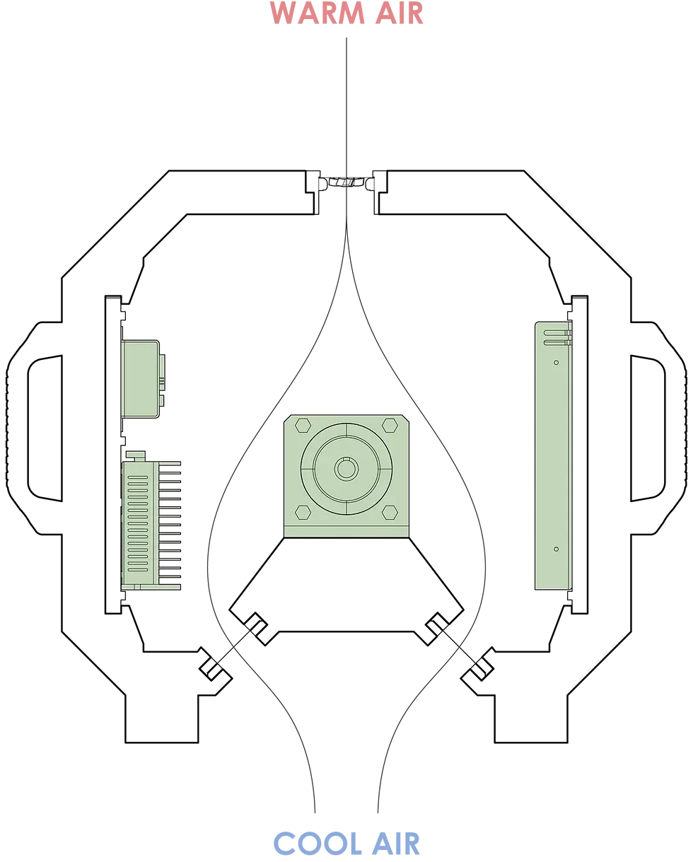
VENTILATION SYSTEM
The electronic components highlighted in green are the parts that need cooling to handle a long day of peristalsis. Based on the internal volume of the main housing, an 80mm fan and opening sizes for two filters were given to me and I worked them into the design.

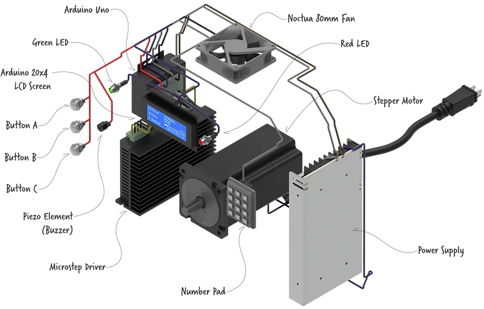
THE PARTS LIST
All the electronics/components were picked out for me and I worked them into the design. I am not an electrician and so the wiring you see here is theoretical but shows possible wire management. The user interface on the screen and the button identity is theoretical. Buttons A-C will change depending on the need, follow the prompts on the screen.